
Mechanical & Manufacturing · 2026-09-12
Final Year Project Ideas for Mechanical Engineering: Design, FEA and Fabrication.
Finding verified final year project ideas in Pakistan for mechanical engineering students involves transitioning CAD assemblies into a fully functional fyp prototype with precision machining, 3D printing, and structural stress analysis.
An engineering guide to developing high-scoring mechanical final year projects in Pakistan, from kinematic mechanism design in SolidWorks to precision CNC machining and 3D printing.
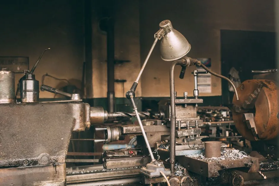
A successful mechanical engineering final year project in Pakistan must combine rigorous CAD kinematic modeling, FEA stress simulation, and precision physical fabrication. University examiners at UET Lahore, NUST SMME, GIKI, PIEAS, and NED Karachi look beyond theoretical computer simulations. They require a functioning mechanical prototype with demonstrable load capacity, verified tolerances, and quantified efficiency metrics. If your team is designing a custom machine, agricultural mechanism, or industrial automation prototype, partnering with an established prototyping facility ensures your hardware survives rigorous committee testing. Explore our dedicated FYP design and development in Pakistan for complete fabrication, machining, and CAD support.
What Evaluation Committees Expect from a Mechanical Engineering Final Year Project
Mechanical capstone committees evaluate projects on mechanical design integrity, kinematic accuracy, structural safety factors, and manufacturing feasibility. In Pakistani universities operating under Outcome-Based Education (OBE) and Washington Accord criteria, students must prove that their physical machine operates reliably without binding, excessive deflection, or thermal runaway in motor drives.
Submitting a purely theoretical simulation report frequently results in grade deductions. To earn top grades, your team must construct a physical assembly. Perform real-world load testing using strain gauges or torque meters, and present empirical graphs comparing actual performance against theoretical mathematical models.
Balancing Computer-Aided Design with Real-World Fabrication
Many student teams spend months refining intricate SolidWorks assemblies, only to find that local machine shops cannot mill the specified complex curves. A professional mechanical engineering workflow requires designing for manufacturing (DFM) from the initial concept phase. Incorporate standard stock dimensions, off-the-shelf fasteners, and accessible manufacturing techniques like 3D printing and laser cutting.
Top High-Scoring Mechanical Engineering Final Year Project Ideas
The most successful mechanical engineering projects address industrial productivity, precision manufacturing, or renewable agricultural automation. Below are four high-impact mechanical project categories engineered to university standards in Pakistan.
| Project Type | Chassis & Materials | Kinematic Mechanism | Drivetrain & Actuation | Repeatability Tolerance |
|---|---|---|---|---|
| Custom 3D Printer | 2020 Aluminium Extrusions | CoreXY Dual-Belt Drive | NEMA 17 + TMC2209 Drivers | ± 0.05 mm |
| Desktop 3-Axis CNC | Aluminium Plate & 3030 V-Slot | SFU1204 Ball Screws | 500W Spindle + NEMA 23 | ± 0.02 mm |
| Automated Harvester | Laser-Cut Mild Steel Sheet | Scissor-Linkage Cutting Head | 12V High-Torque Worm Gear | ± 1.5 mm cutting path |
| Regenerative Dynamometer | Welded Square Tube Frame | Shaft-Coupled Flywheel | BLDC Motor + Eddy Brake | Dynamic torque monitoring |
1. Custom 3D Printer Final Year Project: Dual-Extruder CoreXY Architecture
Designing a custom 3d printer final year project is one of the most complete mechanical challenges available. A high-performance CoreXY 3D printer tests kinematic design, belt tension mechanics, thermodynamic hotend control, and precision linear motion systems.
- Mechanical Architecture: Rigid aluminium cube frame constructed from 2020 or 3030 V-slot extrusions with internal corner brackets to eliminate resonant vibration.
- Motion Transmission: Dual continuous GT2 belts driven by high-torque NEMA 17 stepper motors, riding on MGN12H linear guide rails for ultra-low friction and zero backlash.
- Thermal and Extrusion Design: Direct-drive dual extruder system with all-metal hotends capable of heating to 300 degrees Celsius for industrial filaments like Nylon and Carbon-Fiber PETG.
- Engineering Evidence to Present: Dial-indicator dimensional accuracy measurements, layer-height consistency logs, and thermal gradient analysis of the heated print bed.
2. Desktop 3-Axis CNC Milling Machine for Precision PCB and Aluminium Prototyping
Build a rigid desktop CNC router capable of milling isolation channels on custom copper PCBs and cutting 6061 aluminium plates. This project requires calculating lead-screw critical speeds, ball-screw preloading, and spindle motor torque requirements.
- Drivetrain Calculations: SFU1204 or SFU1605 anti-backlash ball screws paired with flexible shaft couplings to absorb axial motor misalignment.
- Spindle and Drive Electronics: 500W air-cooled DC spindle motor controlled by pulse-width modulation (PWM), driven by dedicated DM542 digital stepper drivers.
- Vibration and Structural Analysis: Running modal frequency simulations in ANSYS to ensure the machine frame natural frequency avoids cutting tool resonant harmonics.
3. Automated Agri-Crop Harvester and Sorter for Smallholder Farms
Address Pakistan's agricultural productivity challenges by developing an automated harvesting mechanism for crops such as tomatoes, citrus, or cotton. The machine features a multi-linkage scissor cutting head, a gentle silicone conveyor belt, and a rotary classification hopper that sorts produce by weight and diameter.
4. Regenerative Braking and Dynamometer Test Bench for Electric Vehicles
Construct a scaled mechanical chassis with a brushless DC motor (BLDC) drivetrain coupled to a heavy flywheel and electromagnetic eddy-current brake. This system captures deceleration kinetic energy, redirecting electrical current back into a lithium-ion battery pack through a bidirectional buck-boost converter.
3D Printing Final Year Projects: Industrial Rapid Prototyping Methods
Modern 3d printing final year projects go far beyond downloading open-source STL files. Advanced capstone projects utilize additive manufacturing to create generative lattice structures, customized orthotic prosthetics, and aerodynamic intake manifolds with internal cooling channels.
Material Selection for Functional Mechanical Prototypes in Pakistan
Choosing the correct filament or resin determines whether your mechanical parts withstand mechanical loading during viva demonstrations:
- PLA (Polylactic Acid): Easy to print with high stiffness and minimal warping. However, it deforms at 55 degrees Celsius and shatters under sharp impacts. Use PLA only for non-load-bearing cosmetic housings.
- PETG (Polyethylene Terephthalate Glycol): Excellent layer adhesion, high impact resistance, and heat tolerance up to 75 degrees Celsius. Ideal for structural brackets, motor mounts, and functional snap-fit joints.
- ABS / ASA: Superior impact resistance and heat stability up to 95 degrees Celsius, but requires an enclosed heated chamber to prevent layer delamination.
- Engineering Photopolymer Resin: Formulated for high-resolution stereolithography (SLA) printing, producing smooth functional gear teeth, fluid manifolds, and miniature kinematic linkages with zero visible layer lines.
Structural Simulation: Validating Mechanical Integrity with FEA
External examiners routinely challenge mechanical students on structural safety margins. In our prototyping lab stress testing, we advise student teams to support every load-bearing member with finite element analysis (FEA) performed in SolidWorks Simulation, ANSYS, or Autodesk Fusion 360.
Key Stress Calculations to Include in Your Technical Thesis
Document the following engineering parameters to defend your mechanical design with confidence:
- Von Mises Stress Distribution: Identify high-stress concentration zones around bolt holes, sharp fillets, and shaft keyways to ensure local stresses remain below material yield strength.
- Factor of Safety (FoS): Maintain a structural factor of safety between 1.8 and 2.5 for static machine components, and between 3.0 and 4.0 for dynamic rotating assemblies subjected to cyclic shock loads.
- Elastic Deflection Analysis: Ensure gantry rails and cantilevered shafts exhibit maximum deflection under 0.05mm under full rated payload to prevent binding in bearings and lead nuts.
Local Material Sourcing and Workshop Capabilities in Pakistan
Building a successful mechanical prototype in Pakistan requires understanding local metalworking and fabrication realities across major industrial centers:
- Extrusions and Fasteners: Aluminium V-slot profiles (2020, 2040) and high-tensile Allen bolts (M3, M4, M5, M6) are readily available in hardware markets like Brandreth Road in Lahore, Saddar in Karachi, and City Saddar Road in Rawalpindi.
- Laser Cutting and CNC Waterjet: Acrylic sheet cutting (3mm to 10mm) and mild steel/aluminium plate cutting can be executed in local prototyping hubs, providing tight dimensional repeatability for motor mounting plates.
- Turning and Milling Operations: Shaft turning, keyway broaching, and bearing seat boring require access to precision lathe machines. PakMEC provides certified machining support to guarantee shaft concentricity and press-fit tolerances.
Need parts made for your project? PakMEC's FYP development support covers CAD, PCB design, 3D printing and fabrication, while the engineering decisions stay with your team.
Frequently Asked Questions
What tolerance is acceptable for a mechanical engineering final year project?
For standard machine assemblies, structural frames require tolerances within plus/minus 0.2mm, while precision linear motion components (lead screws, bearing blocks, guide shafts) require tolerances within plus/minus 0.02mm to prevent mechanical binding and premature wear.
Can our team build an FYP entirely out of 3D-printed parts?
While 3D printing is excellent for housings, custom sensor brackets, and complex ducting, primary load-bearing structural frames should incorporate metal structural extrusions or CNC machined aluminium plates to ensure rigidity and long-term dimensional stability under dynamic loads.
How do we size stepper motors for a custom CNC or 3D printer project?
Calculate total moving mass (gantry plus toolhead), required acceleration (typically 500 to 3000 mm/s squared), and lead-screw pitch. Multiply the resulting force by the pitch lead and divide by 2 pi times mechanical efficiency to establish the holding torque required from your NEMA 17 or NEMA 23 stepper motors.
Need help with the next step?
Need Mechanical Machining or 3D Printing for Your Final Year Project?
PakMEC provides precision mechanical fabrication, SolidWorks CAD design, FEA stress validation, and FDM/resin 3D printing for engineering students across Pakistan.